Testing & Regulating

Transformers for Testing purposes

Testing Equipment, High Voltage Regulating Transformers and HV Testing Transformers

Continuous brush type regulation
1200
V
Secondary voltage up to
750
kV
LV voltage-regulating transformers

with capacity up to 800 kVA; to extend their rating, versatility and application, we also manufacture regulating units which combine fixed-ratio transformers with regulating transformers.
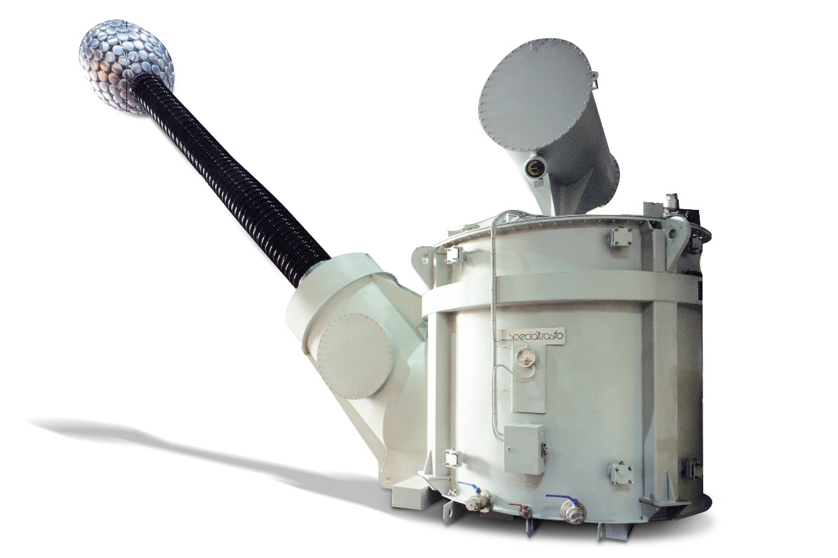
Testing Transfomers

- Short-circuit testing transformers with current up to 300 kA
- HV single-phase high-voltage insulation-testing transformers with secondary voltage up to 750 kV.

Testing Equipment

Engineered and manufactured for all kinds of research laboratories
and routine testing laboratories in industrial applications.

  • testing equipment

    We manufacture testing equipment used in research laboratories as well as in routine testing laboratories. In every laboratory high-voltage A.C. supplies are in common use. As far as the voltage levels are concerned, these may range from some 10 kV only up to more than 750 kV. The testing voltages are usually single-phase voltages to ground. Basically the test system consists of a voltage regulator that supplies a high-voltage transformer. All A.C. test systems operate with mainly capacitive loads, thus the size of the voltage regulator, switchgear, and loading of the power supply line can be significantly reduced by using a reactor to compensate for the capacitance of the test specimen. The main element of the power supply is the voltage regulator; it should have several features which make its selection critical to the performance of the test set:

    • low impedance;
    • linear rate of rise characteristics;
    • lack of distortion of the output voltage.

    The voltage regulators we manufacture meet all these requirements and are the preferred type for this application. Their capacity ranges from 10 to more than 800 kVA. The power supply of the system can be designed the active load component and a small fraction of the total capacitive load by:

    • connecting a tunable reactor and a set of fixed reactors in parallel with the primary of the h.v. transformer. A parallel resonant system is thus obtained. The voltage regulator and the main power supply line provide only the current needed to cover the losses of the system. The h.v. transformer, however, carries the full capacitive load;
    • connecting a tunable h.v. reactor in series with an exciter transformer and the capacitive load. A series resonant system is thus obtained. The exciter transformer, its voltage regulator and the main power supply line provide only the power needed to cover the losses of the system.

    We manufacture dry-type l.v. tunable reactors, oil-immersed l.v. fixed reactors, h.v. testing transformers and h.v. tunable reactors. Tunable reactors are moving-core type. The reactive power varies in the ratio of 1 to 10 in accordance with the length of the air gap within the magnetic circuit. H.v. reactors are oil-immersed and their windings are designed and manufactured like the h.v. windings of an h.v. testing transformer. We are in a position to supply h.v. test systems complete with power supply equipment and control desks. Besides, we manufacture equipment for testing distribution transformers, instrument transformers, A.C. and D.C. motors and so on. Mobile testing equipment is manufactured for h.v. testing and for induced overvoltage testing on large transformers on site. Testing equipment may be supplied complete with computerized control and data acquisition systems.


  • voltage-regulating transformers

    The applications for voltage-regulating transformers and units fall into two broad basic groups:

    • giving a smoothly variable voltage for industrial processes;
    • maintaining constant output levels by compensating automatically for variations in supply voltage.

    The voltage-regulating transformer is a transformer with a continuously tapped secondary winding and with core and coils similar to those of an orthodox transformer. The windings are helical, not toroidal, which allows three-phase units to be built with a three-limb core as in a conventional transformer, rather than by ganging together three single-phase units. A main frame supports the coils, which are fully insulated. The primary winding is placed next to the core while the secondary winding is placed on the outside. The primary comprises two or more separate windings on each core limb, connected in parallel, whose purpose is to reduce the reactance and stray losses in the coil and framework by providing a low impedance path for balancing ampere turns. The turns of the secondary winding are insulated with paper tapes and after a coil has been varnish-impregnated and baked, the outer surface is machined to expose each turn of the winding. A carrier with graphite roller contacts, which can be moved vertically by a chain drive, provides a variable tapping point for the secondary voltage. The complete assembly is oil-immersed, naturally cooled. In the most elementary version of the voltage regulator, the carrier is moved along one side of the secondary coils to provide the required output voltage.

    To extend the rating, versatility and application of regulating transformers, we manufacture regulating units, which combine fixed-ratio transformers with regulating transformers. In this case regulators have their drives arranged so that the carriers on either side of the secondary coils are moved simultaneously, but in opposite directions, over the whole range. This is to provide a variable voltage of either positive or negative polarity, which is injected into the primary windings of a series booster transformer.

    The voltage regulator can be push-button controlled by a reversible motor drive through an integral gearbox. Limit switches are fitted to restrict travel, and a hand-wheel is provided so that manual control can take over when necessary. Voltage stabilizers are a combination of a regulator providing buck-boost output and a series booster transformer. For voltage stabilizers, the regulator driving motor is controlled by a voltage-sensing relay, which detects any variations in the supply and operates the motor in order to correct them.

  • high-voltage testing transformer

    A high-voltage testing transformer is in principle not so different from a single-phase power transformer as regards its thermal rating, kVA output and the fundamental design of its iron core and windings.

    The differences are mainly related to a very compact and well-insulated h.v. winding and a smaller flux density within the core to avoid unnecessarily high magnetizing current, which would produce higher harmonics in the voltage regulator supplying the h.v. testing transformer. The insulation of the h.v. winding is capacitively graded to give even voltage distribution for both alternating voltages and transients during flashovers. The primary winding is usually split up into two sections, which could be switched in series or parallel to increase the regulation range. The iron core is fixed at earth potential as is one terminal of each of the primary and secondary windings.

    The active part of the transformer is normally housed within an earthed metal tank provided with an h.v. bushing. In transformers rated few kVA the core and the coils assembly is housed within an isolated cylinder avoiding the use of the h.v. bushing. Although this design is more compact the heat transfer from the active part to the outside is less efficient. In both designs the tanks are filled with high quality transformer oil.

Case history

Year: 2020

Application: XXXXXX

Lorem ipsum dolor sit amet, consectetur adipiscing elit. Ut elit tellus, luctus nec ullamcorper mattis, pulvinar dapibus leo.
FOTO TESTING 01
FOTO TESTING 02

Year: 2019

Application: XXXXXX

Lorem ipsum dolor sit amet, consectetur adipiscing elit. Ut elit tellus, luctus nec ullamcorper mattis, pulvinar dapibus leo.
FOTO TESTING 03
FOTO TESTING 04